Thursday, June 02, 2022

Error Correction using PID (Proportional Integral Derivative) - The Math

PID or Proportional Integral Derivate is used often times when you need an automated system to self correct. Think for example a robot that has to drive straight or follow a line, or self balance.

Driving or Flying Straight: In this case the robot needs to keep to a certain heading or angle. Various forces might make it deviate from that heading (wind, wheel slip or friction, etc). The difference between the target heading and the actual heading is the error and PID can be used to correct that heading.

Following a line: In line following the robot attempts to follow a dark line to its target. In this case, typically a sensor that senses reflected light is used. The robot attempts to keep the reflected light within a certain range and tries to correct its direction to keep tracking the line. The difference between the amount of reflected light sensed and target reflected light is the error value and used in self correcting the direction the robot is travelling.

Self Balancing Robot: Think about a segway like robot that attempts to self balance using 2 motors. In this case the robot's target orientation is upright and the error is the angle from the vertical plane. The robot then attempts to self correct by applying a force towards the vertical plane. PID again provides the amount of self correcting needed. 

PID is most important in the self balancing example, as one cannot use a constant amount of correction, as the robot would likely topple. This is because while the robot is attempting to balance, the amount of deviation from the vertical plane will vary randomly.

Quad Copter: This is probably the most intuitive applications to work with. Think of a quad copter on the ground. You wish to have it take off and hover at a certain height (eg: 10 feet). When the quad copter first takes off, its altitude sensor will start at 0 feet and the error is 10 feet. The quad copter increases its propeller speed and starts its journey to 10 feet. It will invariably overshoot the target altitude (say 11 feet), so it will have to slow down its propeller to return back to its target of 10 feet. Wind and other factors will keep moving the copter away from its target altitude and so, as the sensor returns its altitude readings, the quad copter will have to continuously change the propeller speed to increase or decrease its altitude.


PID is again a better algorithm to use for a quad-copter trying to attain a target height, compared to a constant correction amount, as it will allow it to get to its target height and maintain it better. 

In a PID based system, the math is trying to reduce the error at every calculation step (or loop) and bring it to its target value. The systems typically never ever reaches the their target value and continuously fluctuates around the target value.


Even though PID uses fancy words like integral and derivate, the math itself is very simple.

Lets go through PID math by its various components:

Proportional

One can use only the proportional part of PID (with I = 0 and D = 0) in many simple systems (eg: line following robot). The job of this component of the PID math is to provide a correction towards the target value.

Kp: constant of proportion (usually called the "proportional gain constant")

SP: Set Point (or the target value we want on the sensor)

PV(t): The process value at time t (or the current sensor value)

E(t) = SP - PV(t) : This is the error at any given time t. (or the error in the graph above).

The proportional value P(t) is calculated as Kp * E(t) or Kp * (SP - PV(t)).

P(t)     = Kp * E(t) 

P(t)     = Kp * (SP - PV(t))

In other words its the error multiplied by a certain tuning factor (Kp). Kp can be used to magnify or dampen the effect of the error on the driving components.

In the diagram below, its Kp * 9ft (where Kp could be any value that you pick, other than 0!). If Kp = 1, then the value would be 9.


Integral

The job of the integral is make larger corrections if the Proportional component is not providing enough of a correction. It accumulates the errors and applies it to the correction. Again a Integral gain constant is used to dampen or magnify the effect of this component.

Ki: integral gain constant

I(t) = Ki * E(t) + I(t-1)

Where I(t-1) is the I(t) that was calculated in the previous cycle. If the terms (t-1) and (t) are confusing, you can also write this as:

I = Ki * E + Iprev


In the above diagram if Ki = 1, then at time = 1:

I = 1 * 9 + 0 = 9     (0, as I starts at 0)

at time = 2,  (now I = 9)

I = 1 * 7 + 9 = 16

Derivate

The job of the derivate is to slow down the effect of the Proportional and Integral components. It attempts to minimize overshoot that can happen as the previous two components attempt to bring the system to the target value. From the graph above its the difference in value of the 2 error values shown above at (t-1) and t.

Kd: derivate gain constant

D(t) = Kd * (E(t) - E(t-1))

or alternatively:

D = Kd * (E - Eprev)


In the above example, if Kd = 1, then at t = 1:

D = 1 * (9-0) = 9

at t=2, E(t-1) or Eprev = 9:

D = 1 * (7-9) = 1 * -2 = -2

Putting it all together:

C(t) = P(t) + I(t) + D(t)    where C is the correction.

C(t) = Kp*E(t) + (Ki*E(t) + Ki*I(t-1)) + Kd*(E(t) - E(t-1))

Going back to our quad-copter example, this is what its flight might have looked like


In fancy math terms this is the PID equation:

The first term is Proportional component, 2nd is Integral and 3rd term is Derivative component.

And as an Algorithm:

  1. Kp = 1, Ki = 1, Kd = 1    (where the values can be different and tuned for your system)
  2. Target = 100              (this is the set-point. This the target value you wish your system to achieve)
  3. CurrentValue = 0       (this is the current sensor measurement or Process value - PV)
  4. ErrPrev = 0
  5. I = 0
  6. while true
    1. Err = Target - CurrentValue(from Sensor)
    2. P = Kp * Err
    3. I = Ki * Err + I
    4. D = Kd * (Err - ErrPrev)
    5. ErrPrev = Err
    6. C = P + I + D
    7. Do something with C    (turn your robot by C degrees, etc).
The above loop is typically continuously evaluated until a certain condition is met (quad-copter has been asked to return home, or robot has reached its target or robot has been running for x minutes, etc).


Wednesday, June 01, 2022

Lego 51515 - Tricky - Understanding the line following code

One of the activities one can code with the Tricky bot is the line follower. But how does the line following code work?

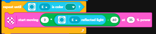
Here is the line following code that tricky uses:


The first line is controls the loop execution and run the line following code until the sensor senses the green piece that is part of the basket.

But what is the the code within the loop doing? In a word: Propotional Line Following Algorithm (ok 4 words!)

Lets break down the code into its various bits:

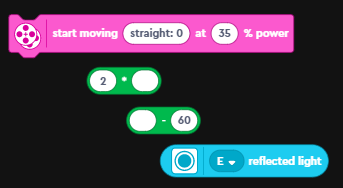
the various bits in that one line of code. order of operations is bottom up


  1. The code uses the sensor in "reflected light" mode. In this mode, the color sensor reports back the amount of light being reflected back to the sensor. Remember dark colors reflect less light compared to light colors.
  2. Next up is the subtract block. The sensor value is one of the operands and the other operand here (the 60) is the target value.

    The idea here is that we want the robot to try and get to the target reflected light value of 60. If it senses more, than it needs to reduce it and if its less, then it needs to increase it. One can call this the "error" value.

  3. The next block is a multiply block. It multiplies the "error" by a constant (in this case 2). One can consider this entire expression upto here, as the "correction value". Here is the complete line:


  4. Next up is the "start moving with steering at power" block. It will move the robot at the specified power (35%) and at the angle defined in the first field. The value we will use for the angle is the "correction value" that we calculated previously. This is what the final line looks like:
How does it all work?
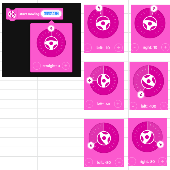
First lets look at how start moving block works. The first input to the block is the direction in which the robot is supposed to move. The values it can take are -100 to 100 (negative values = Left, positive values = Right, 0 = Straight).
The sensor outputs a value between 0 and 100 (0 on black, 100 on white).


The line following algorithm tries to follow the edge of the line, as this is a lot more reliable, than trying to stay completely on the white or on the black part of the line. You should try this as an exercise with your robot (Set target to 0)

Here are the different values for the output angle based on a target value of 60.
Target60
Kp2
SensorErrorAngle CalculationAngleDirection
5552 x (55 - 60)-10Left
65-52 x (65 - 60)10Right
6002 x (60 - 60)0Straight
70-102 x (70 - 60)20Right
80-202 x (80 - 60)40Right
50102 x (50 - 60)-20Left
40202 x (40 - 60)-40Left
100-402 x (100 - 60)80Right
0602 x (0 - 60)-120Left

One thing to note is that with a target value = 60 and Kp = 2, the robot will follow the line when placed on the left side of the line. This is because, values above 60 (more white), will make the robot turn right (towards the line) and values below 60 (more black), will make the robot turn left. If you wanted the robot to travel on the right side of the line what do you think you will have to change? (see answer at the bottom). 

You can play with the above calculations using Google Sheets: https://docs.google.com/spreadsheets/d/1RHkM3w1KmZSh7D-QXvpsda7rRfRzInH4p_jKrHQJQg0/edit?usp=sharing

When you use this piece of code, you might have to change the value of the target (in this case 60) and the multiplier. 

Summary:

Why is this called a proportional line follower? As the robot drifts away from the line, the error value will become larger. We make this error value even larger by using a constant as a multiplier. This error value is then used as the angle to turn the robot. So the larger the difference, the bigger the angle that will applied for steering. Hence the proportional line follower!

So where does the math for all of this come from? There is a concept called PID: Proportional-Integral-Derivative and this concept is used in a lot robotic controllers. In the line-follower, we used just the proportional component of the math. PID uses the following complicated looking formula: 
We used just the first term of the above equation in our code:
If you want to learn more about how PID is used and implemented and the math, read this post of mine: Error Correction using PID (Proportional Integral Derivative) - The Math

You can also learn more about PID here: PID controller - Wikipedia

Answer:
To make the robot travel on the right side of the line, you will have to reverse the output angles. The easiest way to do this is to change the sign of Kp. You would set Kp = -2.


Wednesday, May 18, 2022

Organizer/Storage for Lego Robot Inventor Kit (Mindstorms) 51515


Ever since I got my kid the Lego Robot Inventors 51515 kit, I have been looking for a good way to store the pieces and I think I have finally found the solution thanks to www.RoboticsLearning.com!

On that website, I found a link to a storage organizer system sold at Harbor Freight: Storehouse Toolbox organizer with 4 drawers. If you dont have a harbor freight near you, I think these from Amazon are similar organizer systems:

ABN Tool Box, 10in 1pk - 4 Drawers Toolbox Organizers and Storage, Toolkit Workbench Garage Organizing Set Plastic Chest - - Amazon.com

VonHaus Multi-purpose Small Parts, Crafts or Tool Organizer/Storage Box - 4 Removable Trays & Adjustable Dividers (10.9 x 10.1 x 6.9 inches - Black/Orange) - - Amazon.com

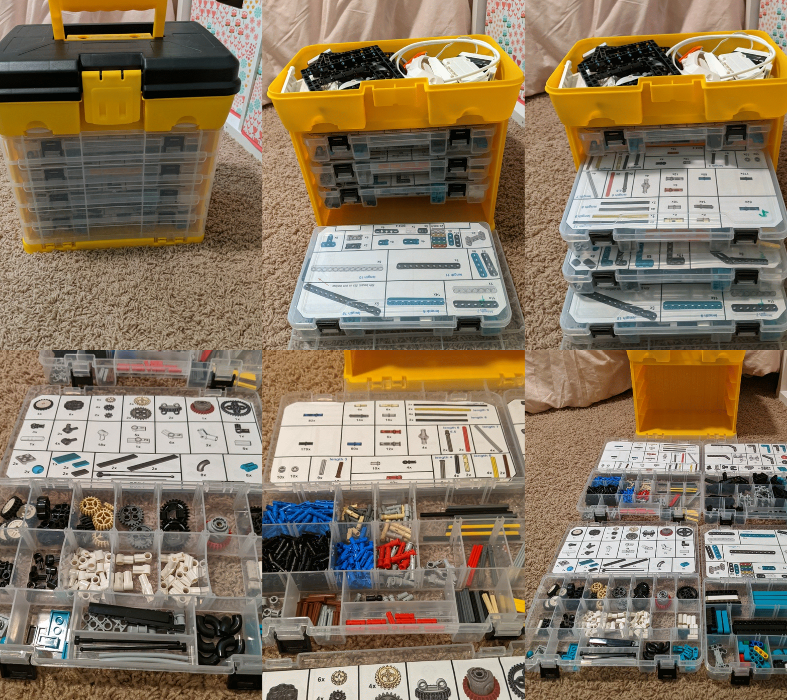
Here are some images of my organized 51515 kit:

https://photos.app.goo.gl/bxrgZ6fAAvpn5eyG7

Here is where you can buy the labels ($10 for the PDF) and find more information on RoboticsLearning.com: LEGO Robot Inventor Set Case Label PDF Files (roboticslearning.com)

Update (11/29/2022): Here is how you can use the above storage box to organize the Spike Prime Kit: https://docs.google.com/presentation/d/10Esa5g_wjFTve83ESnl0FsqPti4y4rMp9Yz4-k-3rP4/edit?usp=sharing

Monday, May 02, 2022

GitHub - Quickly create a patch file

Recently I had to create a patch file to submit to an open source project.

Here is a quick way to do it via the GitHub web-pages.

  1. Go to your pull request (eg: https://github.com/pentaho/pentaho-kettle/pull/8283)
  2. Add ".patch" to the end. Click enter.
  3. This will redirect you to a new page with the patch info with some additional email info, etc.
  4. Copy the entire text and paste it into a file. Save the file with an extension of .patch.
  5. I found that I needed to add a new line at the end of the patch file.
That is your patch file!

To apply the patch file:
  1. Create a new branch from master (or whichever branch the patch is to be applied to).
  2. Switch to the branch.
  3. Run the following command: git apply name_of_patch_file.patch
If you instead want to manually create your patch using GIT:
  1. Switch to the branch with your changes
  2. Run the following command: git diff master > ..\name_of_patch_file.patch


Wednesday, April 27, 2022

AWS Athena's Information_Schema

The information_schema in most database systems is very useful to get information about tables, views, columns that might be available in that db.

Here are the information schema views available. (WARNING: queries against the information_schema views are very slow)


 Schemas:

SELECT

  catalog_name,  schema_name

FROM information_schema.schemata

 Tables:

SELECT

  table_catalog,  table_schema,  table_name,  table_type

FROM information_schema.tables

Columns:

select

  table_catalog,  table_schema,  table_name,  column_name,  data_type,  is_nullable,

  column_default,  comment

from information_schema.columns

order by

  table_catalog,  table_schema,  table_name,  ordinal_position


Retrieved by looking at the PrestoDB test cases: presto/presto-product-tests/src/main/resources/sql-tests/testcases/system at 2ad67dcf000be86ebc5ff7732bbb9994c8e324a8 · prestodb/presto · GitHub 

Pentaho Data Integration - Java Defined Class - Main working sample

 The sample code provided in PDI for "main" doesnt work. Here is the fixed up version:

mypublicnotes/Sample-UserDefinedJavaClass-Main.md at master · rajrao/mypublicnotes (github.com)

Pentaho Data Integration - Stripping characters out of string fields

 Here is a generic method (actually 2) for stripping out characters from all string fields in Pentaho.

mypublicnotes/Sample-Generic-Input-FieldFixerUpper.md at master · rajrao/mypublicnotes (github.com)

These methods are convenient when you are loading a variety of tables or files and you dont know the names of all the string fields ahead of time and so cannot use field based transformations (like Replace in String, etc).

Thursday, February 17, 2022

PowerBi Icons for Diagrams

 I found a couple of awesome resources for PowerBi icons that you can use in diagrams.

1. Official repo of PBI icons: microsoft/PowerBI-Icons: Icons (PNG and SVG) for Power BI (github.com)

2. Marc Lelijveld repo: Marc has provided an xml document that allows you to easily import all the icons into Draw.Io. This makes the whole process extremely easy. marclelijveld/Power-BI-Icons: Icons (PNG and SVG) for Power BI (github.com). The most import link from Marc's repo is the raw link to the xml file: https://raw.githubusercontent.com/marclelijveld/Power-BI-Icons/main/Diagrams.net_PowerBIIcons.xml. This link can be used in Draw.Io via File >>Open Library from >> URL...

Once done, you will get all the icons in the left pane:


Here is more info from Marc's blog: Power BI Icon Library – now includes official icons to use in Draw.io / Diagrams.net – Data – Marc (data-marc.com)

Saturday, January 29, 2022

Kids.youtube.com activate not working

The kids YouTube activation site (https://kids.youtube.come/activate) doesn't seem to be working. I was able to sign in via https://accounts.google.com/o/oauth2/device/usercode?flowName=DeviceOAuth

With 2 kids at home, I feel like a catastrophe has been averted. Hope it helps you.